ZGA5920 (0.1mHz to 15MHz, 10V, 2-channel Impedance/Gain-Phase Analyzer)


Brand: NF
Model Series: ZGA5920 Series

About Product

A/D converted input signals undergo Discrete Fourier Transform (DFT) to calculate complex impedance values and obtain parameters and characteristics specific to the DUT, such as its capacitance, inductance and quality factor. Original NF algorithms are also applied to allow equivalent circuits made up of R, L and C along with the constants for those circuits to be estimated from the complex impedance spectrum obtained by sweeping the frequencies. In servo analysis, data such as the loop cycle gain and closed-loop gain are used to obtain transfer functions (circuit model) and run simulations of the loop cycle gain and closed-loop gain. The NF ZGA5920 Series Impedance/Gain-Phase Analyzer is designed and developed as the comprehensive analyzer for measuring impedance and gain-phase, and for accurately determining the responses and performance of measurement objects. This highly detailed and integrated analysis of a wide range of diverse characteristics makes ZGA5920 Series invaluable not just for materials research and the development of application products, but for problem solving in all sorts of fields.

Product Features

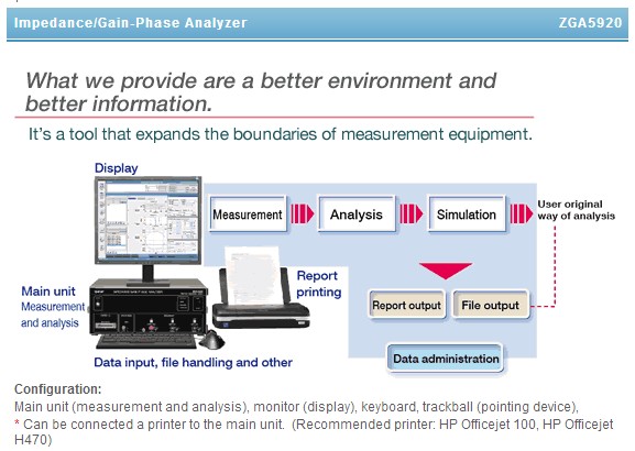
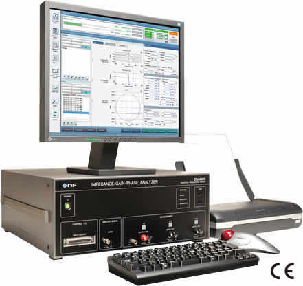
  • Highly reliable measurements for a wide range of measurement objects from the main unit ZGA5920 (for measurement and analysis), monitor (for display), keyboard, trackball (pointing device) and the system can be connected a printer to the main unit when necessary (See photo section)
  • Frequency range: 1mHz to 15MHz
  • Maximum input voltage: 250Vrms
  • Dynamic range: 140dB
  • Extensive range of measurement sweep parameters and high density sweeping of the frequency axis. Sweep parameters: Frequency, AC amplitude, DC bias, time
  • Isolation voltage between all inputs and outputs: 250Vrms
  • Functions available to provide improved measurement data reliability for open/short correction, integration and equalization
  • Amplitude compression (pseudo-constant current output measurement)
  • A wide array of optional peripheral devices are available, such as a power amplifier for amplifying the driving signal and fixtures for the measurement of various items
  • Upgraded measurement and analysis efficiency and smooth utilization of data and smooth system linkages
    • Administration of measurement conditions and results data
    • Automatic repetition measurement
    • Measurement support
    • Linkage with external devices: Equipped with control I/O 8 channels
    • Data logging: Equipped for analog signal input
    • Linkage with the user system: A software developer kit (SDK) is provided
  • Impedance measurement of electronic components
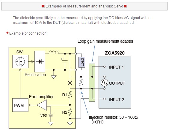
  • Measurement of loop gain of the switching regulator
  • Versatile interfaces: LAN and USB are provided as standard

Product Functions

  • 11 types of measurement objects can be achieved by ZGA5920 on impedance and gain-phase measurements
    • Piezoelectric material
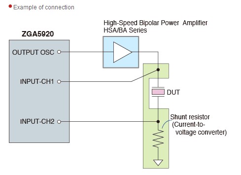
      • The resonance responses can be measured at the same signal level as when the sample is actually used. The signal level of general impedance analyzers is about 1V or lower, so the resulting responses may differ greatly from the responses under actual operating conditions (See photo section)
      • Measurement parameters: Admittance, phase, conductance, susceptance
      • Analysis and simulation: Parameter extraction, matching inductance, parameter simulation
    • Dielectric material
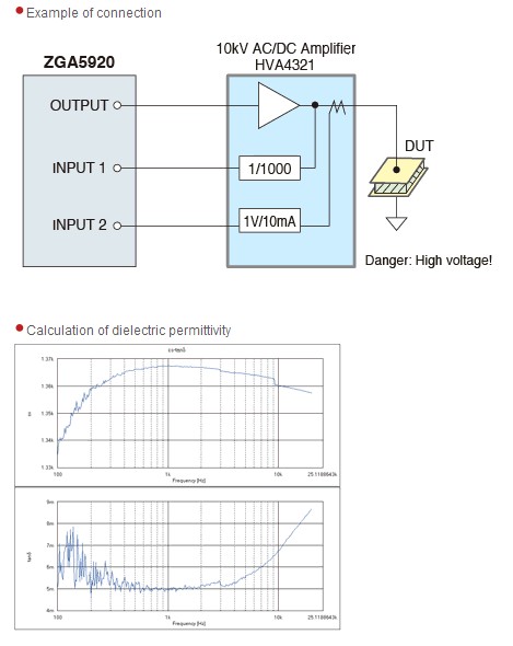
      • The dielectric permittivity can be measured by applying the DC bias/ AC signal with a maximum of 10kV to the DUT (dielectric material) with electrodes attached (See photo section)
      • Measurement parameters: Parallel capacitance, parallel resistance
      • Analysis and simulation: Dielectric permittivity, dissipation factor
    • Magnetic material
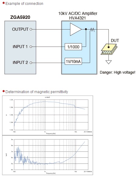
      • Magnetic permittivity can be measured by applying DC bias /AC signals of a maximum of 20A to the DUT (magnetic material) which is wrapped with an inductor (See photo section)
      • Measurement parameters: Series self-inductance, series resistance
      • Analysis and simulation: Magnetic permittivity, dissipation factor
    • Inductor
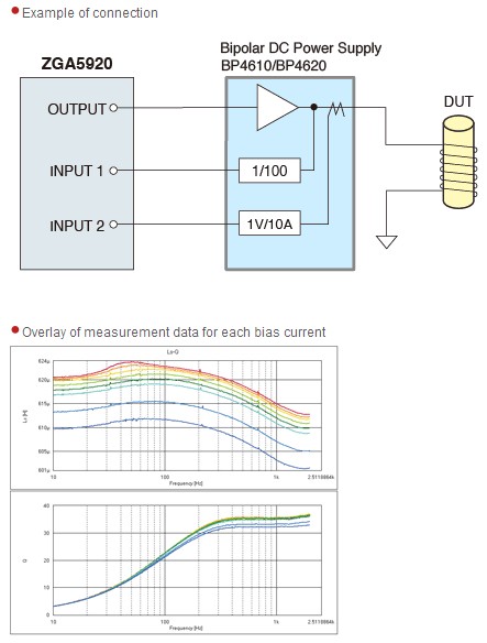
      • The impedance can be measured by applying DC superposed current and a signal current of a maximum of 20A (See photo section)
      • Measurement parameters: Series self-inductance, parallel self-inductance, series resistance, parallel resistance, phase, quality factor
      • Analysis and simulation: Equivalent circuit estimation and simulation
    • Capacitor
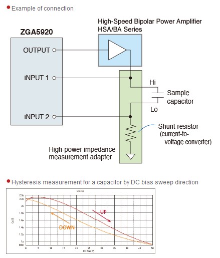
      • The DC bias dependence of laminated ceramic capacitor (those with high dielectric permittivity) can be measured by applying the DC bias sweep at a maximum of ±300V. A high-power impedance measurement adapter facilitates an easy connection for measurement (See photo section)
      • The capacitance measurement is achieved as the DC bias dependence of laminated ceramic capacitor (those with high dielectric permittivity) can be measured by applying the DC bias sweep at a maximum of ±300V. A high-power impedance measurement adapter facilitates an easy connection for measurement (See photo section)
      • Measurement parameters: Series capacitance, parallel capacitance, series resistance, phase, dissipation factor, quality factor
      • Analysis and simulation: Equivalent circuit estimation and simulation
    • Resistor
      • The output impedance can be measured for a power source or an amplifier circuit with one line grounded. LCR meters or impedance analyzers cannot measure the impedance of a DUT single-ended (See photo section)
      • Measurement parameters: Impedance, resistance, reactance, phase
      • Analysis and simulation: Equivalent circuit estimation and simulation
    • Transformer
      • In addition to measuring leakage inductance, it’s possible to measure the mutual inductance and the coupling coefficient. The impedance measurement adapter facilitates an easy connection for measurements (See photo section)
      • Measurement parameters: Leakage inductance, turn ratio
      • Analysis and simulation: Mutual inductance, coupling coefficient
    • Diode
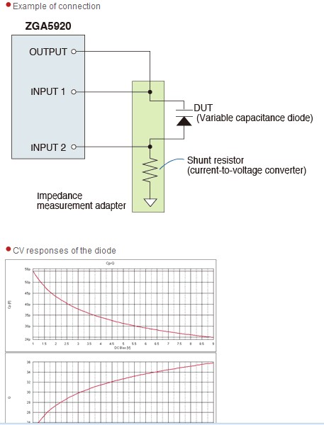
      • The dielectric permittivity can be measured by applying the DC bias/ AC signal with a maximum of 10kV to the DUT (dielectric material) with electrodes attached (See photo section)
      • Measurement parameters: CV characteristics, parallel capacitance, quality factor
      • Analysis and simulation: Tuning characteristics simulation
    • Servo
      • The dielectric permittivity can be measured by applying the DC bias/ AC signal with a maximum of 10kV to the DUT (dielectric material) with electrodes attached (See photo section)
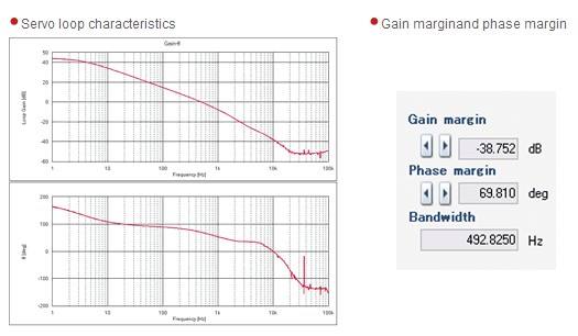
      • Measurement parameters: Loop gain characteristics, closed loop characteristics, open loop characteristics, feedback transfer function
      • Analysis and simulation: Phase margin, gain margin, circuit model identification, circuit model simulation
    • Amplifier Circuit
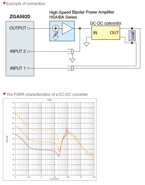
      • The PSRR (Power Supply Rejection Ratio) of a DC-DC converter can be measured (See photo section)
      • Measurement parameters: Gain-phase characteristics, CMRR characteristics, PSRR characteristics, differential gain/phase characteristic, saturation characteristics
      • Analysis and simulation: Transfer function identification, transfer function simulation
    • Filter Circuit
      • Basic parameters such as the -3dB frequency (cutoff frequency) and the pass band ripple are automatically extracted and displayed based on the measured filter responses (See photo section)
      • Measurement parameters: Frequency characteristics
      • Analysis and simulation: Transfer function identification, transfer function simulation
  • Measurement, analysis and simulation
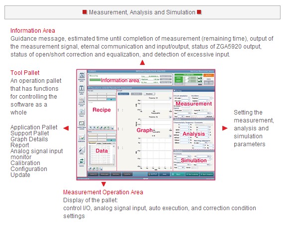
    • Information area: Guidance message, estimated time until completion of measurement (remaining time), output of the measurement signal, external communication and input/output, status of ZGA5920 output, status of open/short correction and equalization and detection of excessive input (See photo section)
    • Tool pallet: An operation pallet that has functions for controlling the software as a whole (See photo section)
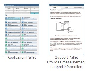
    • Preparation: From your first use of ZGA5920, the measurement objects and measurement parameters are easily selected on the Application Pallet. The measurement, analysis and simulation windows can be directly activated whenever the power is turned on after that. Measurement support information is provided on the Support Pallet (See photo section)
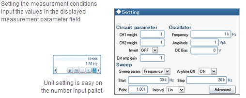
    • Setting the measurement conditions: Input the values in the displayed measurement parameter field (See photo section)
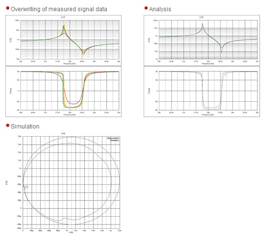
    • Graph display of the measurement result: The measurement results are displayed as a graph. “Graph Details” lists all the types of graphs that can be used to display the measurement results. It’s also equipped with a graph overwriting function and a marker for reading the values (See photo section)
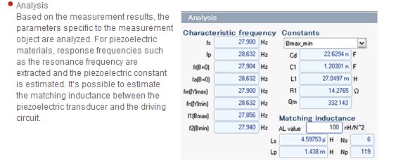
    • Analysis: Based on the measurement results, the parameters specific to the measurement object are analyzed. For piezoelectric materials, response frequencies such as the resonance frequency are extracted and the piezoelectric constant is estimated. It’s possible to estimate the matching inductance between the piezoelectric transducer and the driving circuit (See photo section)
    • Simulation: Simulation can be executed by freely changing the parameters. The characteristics are displayed on the graph (See photo section)
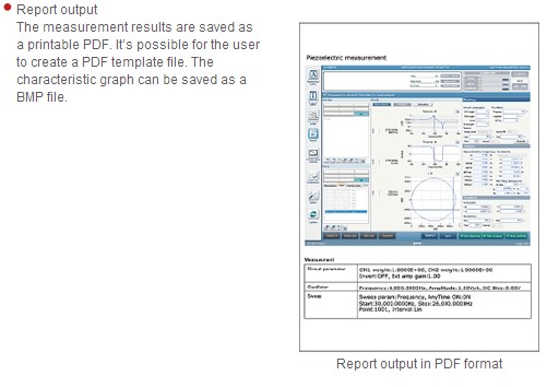
    • Report output: The measurement results are saved as a printable PDF. It’s possible for the user to create a PDF template file. The characteristic graph can be saved as a BMP file (See photo section)
  • Data administration
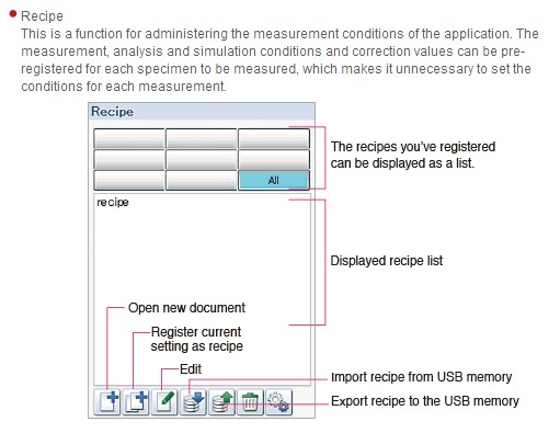
    • Recipe: This is a function for administering the measurement conditions of the application. The measurement, analysis and simulation conditions and correction values can be pre-registered for each specimen to be measured, which makes it unnecessary to set the conditions for each measurement (See photo section)
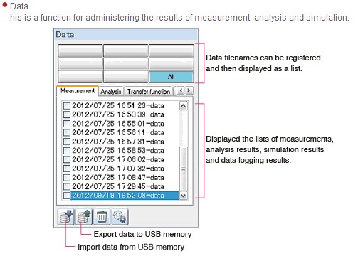
    • Data: This is a function for administering the results of measurement, analysis and simulation (See photo section)
    • In note, recipe, measurement and analysis data, simulation data, and analog input data are saved in XML format, and transfer function data are saved in TXT format. The import and export of various data is possible by using the dedicated utility software or USB memory

Product Application

  • Ideal for measuring, evaluating and testing materials and electronic components such as piezoelectric material, capacitor and inductor
  • Evaluation and research of response characteristics of electronic circuits such as filter and amplifier
  • Supports measurement of power devices and high-voltage circuits
  • Capability in ultra-low frequency measurement
  • Impedance measurement of electronic components
  • Measurement of loop gain of the switching regulator
  • Evaluation of negative feedback characteristics of switching power supply and inverter

Standard Accessories

  1. LAN Interface
  2. USB Interface
  3. ZGA5920 Instruction Manual
  4. CD-ROM
  5. ZGA5920 Utility Software
  6. ZGA5920 Software Development Kit (SDK)
  7. 3 pcs of Signal Cable (BNC-BNC 50Ω, 1m, 250Vrms CAT I)
  8. BNC T-Branch (250Vrms)
  9. Ferrite Core (Clamp Type)
  10. Power Cable

Product Options

  1. 5055: Signal Injector Probe
  2. PA-001-0368: Impedance Measuring Adapter
  3. PA-001-0369: Loop Gain Measuring Adapter
  4. PA-001-0370: Shunt Register
  5. PA-001-0419: High Withstand Voltage Clip Set (3pcs Pair)
  6. PA-001-0420: High Withstand Voltage Alligator Clip Cable Set (Small, 3pcs Pair)
  7. PA-001-0421: High Withstand Voltage Alligator Clip Cable Set (Large, 3pcs Pair)
  8. PA-001-0422: Basket Worm Clip Cable Set (3pcs Pair)
  9. PA-001-1838: Test Fixture Adapter (1Ω)
  10. PA-001-1839: Test Fixture Adapter (100Ω)
  11. PA-001-1840: High Power Impedance Measuring Adapter (1Ω)
  12. PA-001-1841: High Power Impedance Measuring Adapter (100Ω)
  13. PC-001-4503: High Withstand Voltage BNC Adapter (T-branch)
  14. PC-002-3347: High Withstand Voltage BNC Cable
  15. PC-007-0364: High Withstand Voltage Plug-Receptacle BNC Cable
  16. PC-007-1490: Kelvin Clip for Impedance Measuring Adapter (For Change)
  17. PC-007-1922: Loop Gain Measuring Adapter Clip Cable (For Change)

Related Catalog

Specification-of-ZGA5920-Series

Our Company

Miko, established in 1980, is a leading instrumentation distributor in Hong Kong and China.

Over the years, we have been fully engaged in the sales and marketing of electronic T&M instruments in the territory. Our market sector coverage includes telecommunication, power, data communication, audio, broadcasting and education.